
Results: CFD Analysis of a Rotating Spur Gear System
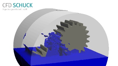
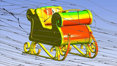
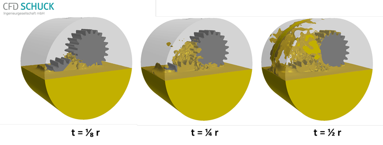
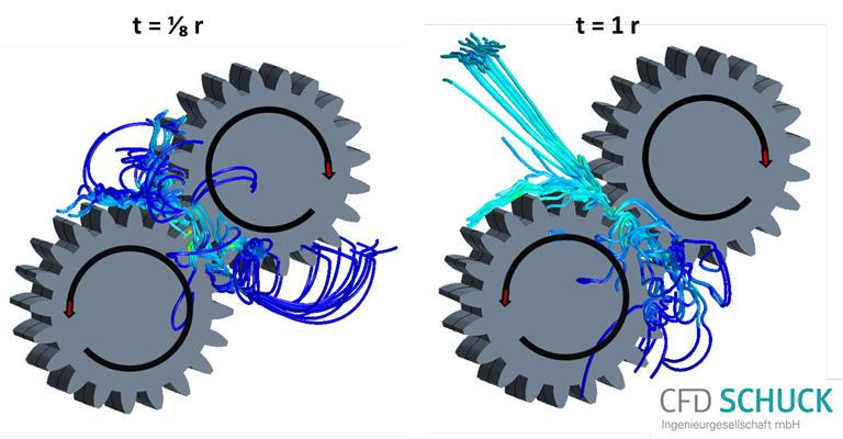
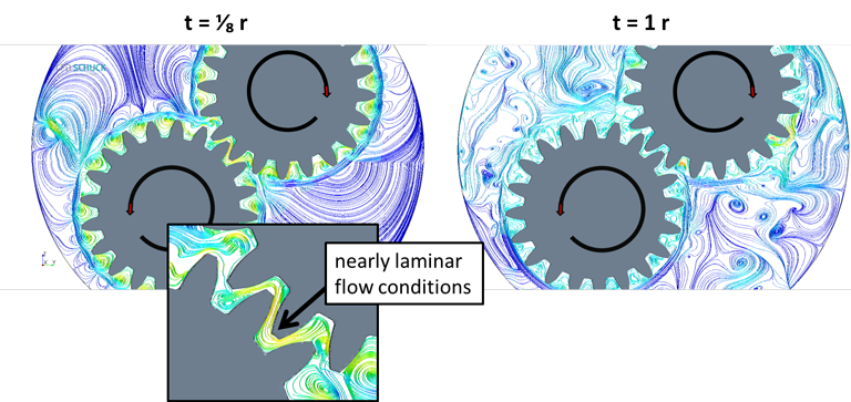
As a consequence of the high computational demand of this simulation, only two full revolutions (r) of the gears were simulated for all cases. At that point, the flow field has not quite reached steady state conditions but the oil was already forced out of the gear teeth regions as a result of the high rotational kinetic energy in the system. In our opinion, important flow processes have already occurred at that point in time, determining oil distribution on gear flanks, friction between gearwheels, and oil distribution in the gearbox. Figure 3 shows the oil distribution in the gearbox for the middle oil level after 1/8, 1/4, and 1/2 r and this gives a good indication of how much oil was already splashed out of the oil sump after a short time interval. Furthermore, the results from the simulation enable a detailed transient assessment of the velocity streamlines and flow fields (figure 4) as well as pressure distribution in the system (figure 5), shown for the middle oil level. The streamlines in figure 4a represent transient flow features between the intermeshing gears and thus give some indication on whether the oil flow is still sufficient for lubrication. Figure 4b demonstrates changes in the velocity flow field with time. At the beginning of the simulation (1/8 r), the field was characterized by circulation between adjacent gear teeth and nearly laminar flow conditions in the intermeshing gear region. However, after 1 r, turbulent structures already dominate the flow field in the gearbox.
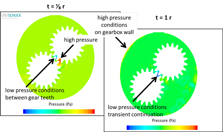
The pressure conditions in figure 5 indicate that initially, most of the oil amount remains in the oil sump and thus, high amounts of oil could be squeezed into the interstitial gear region. After 1 r, the oil splashing already has pressure effects on the gearbox housing, while the low pressure conditions in the intermeshing gear region indicate oil suction into the gap.
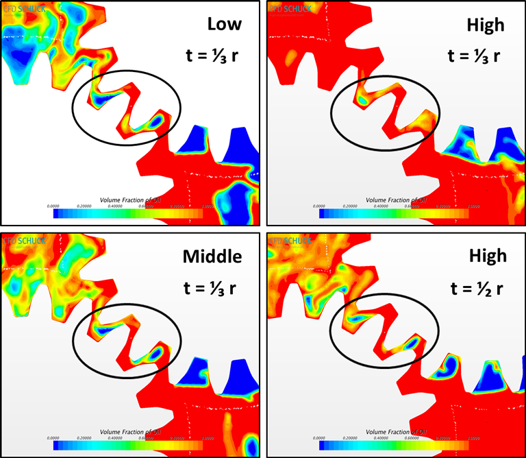
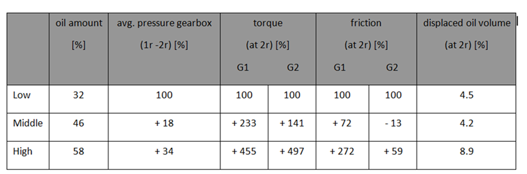
The challenge of optimizing lubrication and of finding the best oil filling height is the minimization of splashing effects (displaced oil volume), torques, and friction (shown in table 1) while maximizing the oil film on gear flanks. The simulation results enabled a qualitative and quantitative assessment of the best filling level of oil in the system. In all cases (low, middle, and high oil level), the inclusion of air bubbles in interstitial gear regions becomes obvious at the latest after 1/2 r (figure 6).
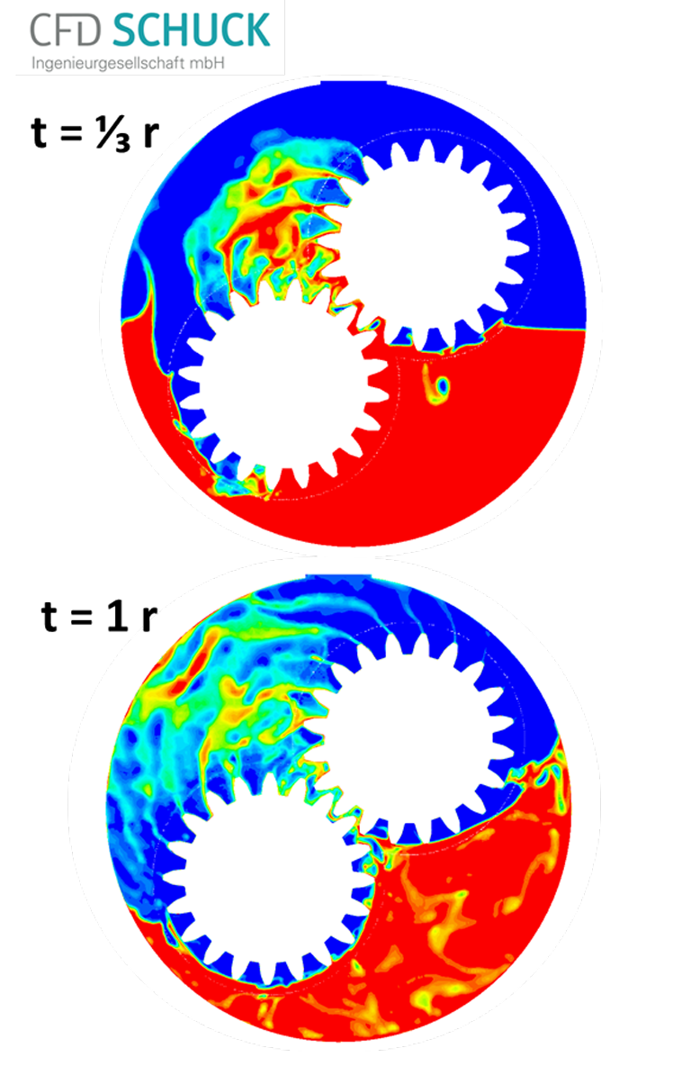
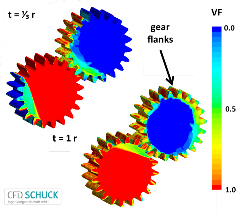
Figure 7 depicts the oil distribution in the box (7a) and on gear flanks (7b) after 1/3 r and 1 r for the middle oil level.
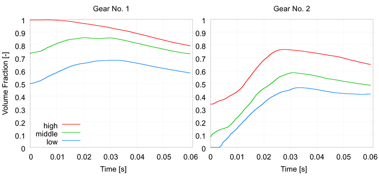
The diagram in figure 8 compares the volume fractions (VF) of oil on gear flanks between the three different filling heights indicating that the highest oil level resulted in the highest VF of oil on the gear flanks. On the other hand, the increase/decrease of the VF curves was not proportional between the different filling levels (figure 8) and the middle filling level resulted in good values when compared to the highest level for gear 1.
The comparison in Table 1 also indicated that the middle level resulted in small oil splashing effects compared to the available oil amount in the system. Pressure, torque, and friction conditions were also comparably low for this filling depth.
The effect of including a linear ramp of the rotational frequency in the simulations was also studied and showed only a small influence on the oil fraction on the gear flanks (results not shown).
Conclusion and Future Work
Transient flow fields, pressures, and torques in the gear-box and in the intermeshing gear region have been efficiently and effectively studied using the presented CFD method. The applied method offered a convenient way to study the influence of different oil filling heights on the oil flow in the gearbox and on the volume fraction of oil on gear flanks. Due to their high specific heat capacity, liquid lubricants also fulfill important functions concerning the cooling system of a gearbox. Future work will therefore include oil temperature simulation and heat dissipation in the gear-box as well as heat conduction at the gear-box wall and at the gear flanks. These results served as a case study and experimental data will be essential for further model validation.
More around this topic...
In the same section


© HPC Today 2024 - All rights reserved.
Thank you for reading HPC Today.


