
Netgear manufactures 10 Gigabit Ethernet switches for Top-of-Rack and Aggregation applications. They reduce maintenance and administrative costs, allowing IT to focus on other business-critical tasks. They help growing companies support rising bandwidth requirements, new applications, and the demands of a fast-paced business environment.
The IEEE standard for 10 Gigabit Ethernet (10GbE), IEEE Standard 802.3ae- 2002, was ratified eight years ago. Almost immediately, large enterprises started confidently deploying 10GbE in their corporate backbones, data centers, and server farms to support high-bandwidth, mission-critical applications.
Over the years, improvements in 10GbE technology, price, and performance have extended its reach beyond enterprise data centers to midmarket networks. Increasing bandwidth requirements and the growth of enterprise applications are also driving broader deployments of 10 Gigabit Ethernet.
Here is a list of 10 important things for achieving a reliable, affordable, and simple 10 Gigabit Ethernet deployment.
10 Gigabit Ethernet and the Server Edge: Better Efficiency
Midmarket organizations are optimizing their data centers and server rooms by consolidating servers to free up space, power, and management overhead. The first step usually involves consolidating applications onto fewer servers than the old single-application-per-server paradigm. Often, the next step is server virtualization.
Server virtualization supports several applications and operating systems on a single sever by defining multiple virtual machines (VMs) on the server. Each virtual machine operates like a standalone, physical machine, yet shares the physical server processing power, ensuring no processing power is wasted. IT departments can reduce server inventory, better utilize servers, and manage resources more efficiently.
Server virtualization relies heavily on networking and storage. Virtual machines grow and require larger amounts of storage than one physical server can provide. Network attached storage (NAS) or storage area networks (SANs) provide additional, dedicated storage for virtual machines. Connectivity between servers and storage must be fast to avoid bottlenecks. 10GbE provides the fastest interconnectivity for virtualized environments.
10 Gigabit Ethernet SAN versus Fibre Channel: Simpler and More Cost-Effective
There are three types of storage in a network: Direct-attached storage (DAS), NAS, and SAN. Each has its advantages, but SAN is emerging as the most flexible and scalable solution for data centers and high-density computing applications. The main drawback to SAN has been the expense and specially trained staff necessary for installing and maintaining the Fibre Channel (FC) interconnect fabric. Nonetheless, SANs with Fibre Channel have become well established in large enterprises.
A new standard, the Internet Small Computer System Interface (iSCSI), is making 10 Gigabit Ethernet an attractive, alternative interconnect fabric for SAN applications. iSCSI is an extension of the SCSI protocol used for block transfers in most storage devices and Fibre Channel. The Internet extension defines protocols for extending block transfers over IP, allowing standard Ethernet infrastructure to be used as a SAN fabric. Basic iSCSI is supported in most operating systems today. The latest iSCSI capabilities allow 10 Gigabit Ethernet to compare very favorably to Fibre Channel as a SAN interconnect fabric:
- Reduced Equipment and Management Costs: 10GbE networking components are less expensive than highly specialized Fibre Channel components and do not require a specialized skill set for installation and management.
- Enhanced Server Management: iSCSI remote boot eliminates booting each server from its own direct-attached disk. Instead, servers can boot from an operating system image on the SAN. This is particularly advantageous for using diskless servers in rack-mount or blade server applications.
- Improved Disaster Recovery: All information on a local SAN — including boot information, operating system images, applications, and data—can be duplicated on a remote SAN for quick and complete disaster recovery
- Excellent Performance: Even transactional virtual machines, such as databases, can run over 10 Gigabit Ethernet and iSCSI SAN, without compromising performance.
10 Gigabit Ethernet and the Aggregation Layer: Reduce Bottlenecks
Until recently, network design best practices recommended equipping the edge with Fast Ethernet (100BASE-T), and using Gigabit uplinks to either the core (for two-tiered network architectures) or aggregation layer (for three-tiered networks). Today, traffic at the edge of the network has increased dramatically. Bandwidth-intensive applications have multiplied, and Gigabit Ethernet to the desktop has become more popular as its price has decreased. Broader adoption of Gigabit Ethernet to the desktop has increased the oversubscription ratios of the rest of the network. The result: a bottleneck between large amounts of Gigabit traffic at the edge of the network, and the aggregation layer or core.
10 Gigabit Ethernet allows the aggregation layer to scale to meet the increasing demands of users and applications. It can help bring oversubscription ratios back in line with network-design best practices, and provides some important advantages over aggregating multiple Gigabit Ethernet links:
- Less Fiber Usage: A 10 Gigabit Ethernet link uses fewer fiber strands compared with Gigabit Ethernet aggregation, which uses one fiber strand per Gigabit Ethernet link. Using 10 Gigabit Ethernet reduces cabling complexity and uses existing fiber cabling efficiently, a consideration if laying additional fiber is cost-prohibitive.
- Greater Support for Large Streams: Traffic over aggregated 1 Gigabit Ethernet links can be limited to 1 Gbps streams because of packet sequencing requirements on end devices. 10 Gigabit Ethernet can more effectively support applications that generate multi Gigabit streams due to the greater capacity in a single 10 Gigabit Ethernet link.
- Longer Deployment Lifetimes: 10 Gigabit Ethernet provides greater scalability than multiple Gigabit Ethernet links, resulting in a more future-proof network. Up to eight 10 Gigabit Ethernet links can be aggregated into a virtual 80-Gbps connection.
10 Gigabit Ethernet and Fiber Cabling Choices
There are three important considerations for any fiber cable deployment:
- The type of fiber cable (for example single-mode)
- The type of 10 Gigabit Ethernet physical interface (for example 10GBase-SR)
- The type of optics module form factor (for example XFP)
The following tables summarize the standard fiber cables, physical interfaces, and form factors applicable to 10 Gigabit Ethernet.
| Multi-Mode MMF | 62.5/125µm (OM1 grade) fiber | Previous industry standard |
| 50/125µm (OM2 grade) fiber | Previous industry standard | |
| 50/125µm (OM3 grade) fiber | Current industry standard (new installations) | |
| Single-Mode SMF | 9/125µm fiber | Current industry standard |
| Multi-Mode MMF | 10GBase-LX4 | Maximum range of 300m (980ft) | Previous industry standard |
| 10GBase-SR | “Short Range” up to 300m (980ft) | Current industry standard | |
| 10GBase-LRM | “Long Reach Multimode” up to 260m (850ft) | Current industry standard | |
| Single-Mode SMF | 10GBase-LX4 | Maximum range of 10km (6.2mi) | Previous industry standard |
| 10GBase-LR | “Long Reach” up to 10km (6.2mi) | Current industry standard | |
| 10GBase-ER | “Extended Reach” up to 40km (25mi) | Current industry standard |
| XENPACK | Large form factor | Previous industry standard |
| X2 (XPACK) | Smaller form factor than XENPACK | Previous industry standard |
| XFP | Smaller form factor than X2 | Current industry standard |
| SFP+ | Smallest form factor | Current industry standard |
| Multi-Mode MMF | Single-Mode SMF | |||
| 10 GE PHY | 62.5/125µm OM1 | 50/125µm OM2 | 50/125µm OM3 | 9/125µm |
| 10GBase-LX4 | 300m (980ft) | 240m (790ft) | 240m (790ft) | 10km (6.2mi) |
| 10GBase-SR | 33m (108ft) | 33m (108ft) | 300m (980ft) | – |
| 10GBase-LRM | 220m (720ft) | 220m (720ft) | 260m (720ft) | – |
| 10GBase-LR | 33m (108ft) | 33m (108ft) | 33m (108ft) | 10km (6.2mi) |
| 10GBase-ER | – | – | – | 40km (25mi) |
Form factor options are interoperable as long as the 10 Gigabit Ethernet physical interface type is the same on both ends of the fiber link. For example, it is possible to deploy a fiber link with one 10GBase-SR XFP optics on the left, and one 10GBase-SR SFP+ optics on the right. However, one 10GBase-SR SFP+ optics cannot connect to one 10GBase-LRM SFP+ optics at the other end of the link.
10 Gigabit Ethernet and Copper Cabling Choices
As switching standards mature and copper cabling standards catch up, the use of copper cabling for 10GbE is becoming more common. Currently, there are three different copper cabling technologies for 10 Gigabit Ethernet, each with different price and performance capabilities (see Table 5). Although fiber (SFP+ optics) delivers the lowest latency, many IT departments use copper cabling for switch-to-switch or switch-to-server connections.
| Media | Copper cable | Range (max) | Average latency | |
| CX4 | Twin-ax copper | 15m (49ft) | 0.1 µs | IEEE 802.3ak-2004 |
| SFP+Direct Attach | Twin-ax copper SFP+CU | 10m (33ft) | 0.1 µs | MSA SFF-8431 housing |
| 10GBase-T | Twisted pair CAT6 RJ45 | 30m (98ft)—50m (164ft) | >1.5 µs | IEEE 802.3an-2006 |
| Twisted pair CAT6a RJ45 | 100m (98ft) | >1 µs | ||
| Twister pair CAT7 GG45 | 100m (98ft) | >1 µs |
10GBase-CX4, published in 2004, was the first 10 Gigabit Ethernet copper standard. CX4 was relatively economical and allowed for very low latency. Its disadvantage was a too-large form factor for high density port counts in aggregation switches.
SFP+ is the latest standard for optical transceivers. 10 Gb SFP+Cu Direct Attach Cables (DAC) connect directly into an SFP+ housing. This new copper solution has become the connectivity of choice for servers and storage devices in a rack because of its low latency, small form factor, and reasonable cost.
10GBase-T or IEEE 802.3an-2006 was released in 2006 to run 10 Gigabit Ethernet over CAT6a and CAT7 copper cabling up to 100 meters. While promising, 10GBase-T still needs technology improvements to lower its cost, power consumption, and latency.
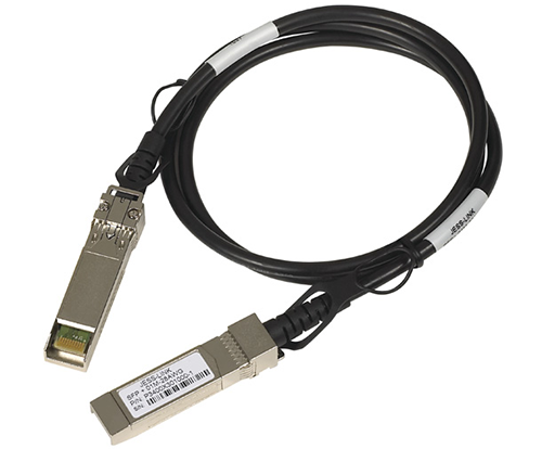
10 Gigabit Ethernet and the SFP+ Makeover: Direct Attach Cables are Convenient for Short Runs
SFP+ Direct Attach Cables integrate SFP+ compatible connectors with a copper cable into a low-latency, energy-efficient, and low-cost solution. DAC are available in several lengths up to 10 meters (33 ft) and are the currently the best cabling option for short 10 Gigabit Ethernet connections (see Figure 1).
For Top-of-Rack Applications
Top-of-Rack (ToR) switches use the SFP+ form factor to provide high port density 10 Gigabit Ethernet in an efficient 1U form factor. Server and network storage vendors use 10 Gigabit SFP+ network adapters on their equipment for the same reason. DAC simplify rack cabling and termination. Each server and network storage device can be directly connected to the ToR switch, eliminating the need for intermediate patch panels. DAC are flexible enough for vertical cabling management within the rack architecture. The only cabling outside the rack is the ToR switch uplink connection to the aggregation layer, making moving racks easy.
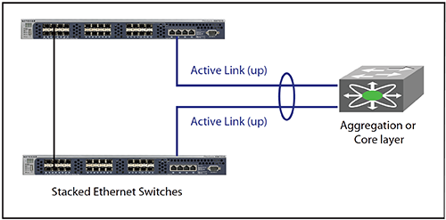
10 Gigabit Ethernet and Link Aggregation Offers Redundancy and Resiliency
Port trunking or link aggregation is not new. Previous IEEE standards defined ways to aggregate multiple Ethernet ports onto a single logical link to improve overall connection speed and availability.
The IEEE Link Aggregation Control Protocol (LACP) standard defines a way of bundling several physical ports over one logical channel. Most 10 Gigabit Ethernet servers and network storage devices today have multiple ports and support Active-Active LACP port teaming. However, the primary concern for servers is redundancy, and the LACP standard only defines Active-Active server teaming to the same switch, creating a single point of failure if the switch goes offline. For this reason, server connections are typically configured in failover mode, with an active connection to the first switch, and a redundant connection to a second switch which is activated only when the first connection is down.
Several complex, expensive, and proprietary technologies do provide LACP teaming across several stand-alone, different switches. However, from a deployment standpoint, it is far easier to implement a distributed LACP solution with stackable switches that allow link aggregation across the stack. In this configuration, the stack acts as a single logical switch and link aggregation is seamless.
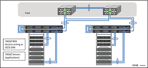
10 Gigabit Ethernet and Top-of-Rack Best Practice
Figure 3 shows a stackable 10 Gigabit Ethernet ToR switching solution enabling cost-effective SAN connectivity for servers and network storage. LACP functionality provides better availability and redundancy for servers and storage in addition to better performance. Since the servers are virtualized, Active-Active server teaming can be distributed across two stacked switches, ensuring physical redundancy for the server while it is connected to the same logical switch. LACP support also provides failover protection if one physical link goes down, while iSCSI traffic load balancing ensures greater transmission throughput with lower latency.
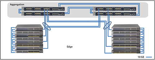
10 Gigabit Ethernet and Distribution Layer Best Practice
Supporting Gigabit Ethernet to the desktop requires a high-bandwidth, efficient and resilient solution. Figure 4 shows Gigabit access switches with 10 Gigabit uplinks and stackable 10 Gigabit aggregation switches. As with the TOR best practice, LACP active-active teaming is distributed across four stacked switches, delivering excellent resiliency and availability while providing a connection to the same logical switch. At the edge, stacks of access switches are virtualized into a single switch, reducing configuration and management overhead. Network load balancing ensures traffic is dynamically distributed across physical links. Finally, LACP failover protection is more efficient than using the spanning tree protocol for link redundancy. Spanning tree backup links are down when active links are up, whereas all LACP links are up at the same time, offering better aggregated bandwidth and seamless redundancy.
More around this topic...
In the same section


© HPC Today 2024 - All rights reserved.
Thank you for reading HPC Today.


